
Golden Gate Graphics
Your Go-To PCB Design Service Bureau using Altium Designer for Layout and Schematics
What Customers are Saying About Golden Gate Graphics PCB Design
- "John is a highly skilled PCB board designer. John and his staff are great people, and I recommend his company for any PCB layout task you may have."
~Eric O, Electrical Engineer. - "Reliable, precise and meticulous; our large, complex design was virtually error free the very first iteration."
~Phil C, Electrical Engineer.
The Sky is the Middle
People say "The sky is the limit" when they mean "We can do anything we want or imagine." But add space exploration and the sky is no longer the limit. That's a bit beyond blue sky.
We Can Handle Any Technology
Printed circuit boards we have designed at Golden Gate Graphics have at one time or another found their way onto space exploration rockets, including one pointed at the planet Mercury, the space shuttle and space-to-ground communications systems. They have been used to implement the electronics in everything from battery monitoring systems in drone helicopters to chip factories. They have been in airplane navigation radio systems, telescope tracking systems and geophysical probes.
From outer space to underground, we cover the scope of technology. That's why we can say at Golden Gate Graphics: "The Sky is the Middle."
Of course we just laid-out the printed circuit board artwork. The real geniuses are the electrical engineers we work with. Our artwork merely helped to implement their visions by making them manufacturable. We would like to work with you in your next dreamscape.
Example Printed Circuit Boards Designed by Golden Gate Graphics
The pictures below include actual boards and design views. The 3D capabilities of Altium Designer 25 and earlier not only include export of 3D models of the entire board, but also design rule checking of placement using both horizontal and vertical clearance constraints. To our knowledge, this is currently the only PCB design software capable of using 3D bodies in real-time clearance checking.
We typically make the 3D models in our component footprints translucent so that we can see what is underneath them.
Read more on techniques we use in 3D modeling to get designs to come out right.

Top side 3D design view: Round multi-function board; Bluetooth, ANT and WiFi radios, power supplies, digital signal processing and ultra sound. Really! All that on one board! - In the center of the figure above, you can see the 3D axes in red blue and green. This is the origin of the PCB file. Using the center for the origin works best with round boards. With Altium Designer you can implement polar coordinates indirectly, as long as you know the formulas for converting cartesian to polar.
- To convert Cartesian coordinates (x, y) to polar coordinates (r, θ), use the formulas: r = √(x² + y²) and θ = arctan(y / x).

Same board showing an external model that acts as a height constraint in vertical clearance checking. This portion of the assembly held the battery. 
Bottom side 3D design view: Round multi-function board; Bluetooth, ANT and WiFi radios, power supplies, digital signal processing and ultra sound. - Some of our 3D bodies are translucent. Altium Designer allows one to adjust the level of transparency of 3d bodies. Thus, the bodies still function for real-time three-dimensional clearance checking and allow us to see what is underneath them.
-
3D Modeling Example

Click image for illustration of how Golden Gate Graphics uses Altium Designer's 3D modeling capabilities. 
Top side 2D design view: Round multi-function board; Bluetooth, ANT and WiFi radios, power supplies, digital signal processing and ultra sound. Top1533-768hIq70.webp "Adapter board - top")
Adapter board - top Bottom1533-768hIq70.webp "Adapter board - bottom")
Adapter board - bottom 
Adapter board - 3D design view - top 
Adapter board - 3D design view - bottom 
Adapter board - 2D design view -
")
Pressure sensors, mixed analog and digital, top side - showing prototyping adaptions (blue wires) 
3D design view - top. 
Mixed analog and digital, bottom side showing prototyping adaptions and COTS modules. 
3D design view - bottom, showing modules, with custom module in lower left placed as a component. (Board solder mask on bottom shown in blue for contrast.) 
Location of future custom module. 
3D design view of future custom module - top 
3D design view of future custom module - bottom 
2D design view of main board 
2D design view of future custom module Halo system boards for Trillium DUT (Device Under Test) for testing in chip manufacturing plant.
- For more information see DUT Halo/Daughter Card System

Assortment of DUT daughter cards with the halo board they fit into below 
Bottom side of a DUT board, which is the side that contacts the test fixture. 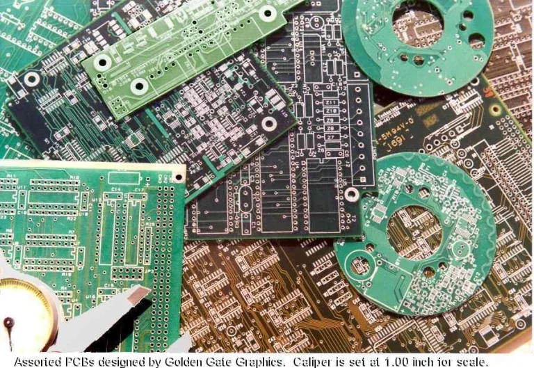
Click image for expanded view of assortment of bare boards designed by Golden Gate Graphics prior to 2001.

3D Modeling Example
Golden Gate Graphics resides in Aurora, a suburb of Denver located in the middle of the
Rocky Mountain Front-Range High-Tech Corridor
, which includes the following
Colorado cities from south to north:
Colorado Springs, Monument, Castle Rock, Highlands Ranch, Centennial, Englewood, Littleton, Denver, Lakewood, Golden, Aurora, Broomfield, Louisville, Lafayette, Boulder, Longmont, Loveland, Ft. Collins and Greeley.
 |
 |
| Full site is mobile responsive as of 3/22/25. Last update: Wednesday, April 16, 2025.
Copyright © 2025 John Walt Childers, IPC-CID. All Rights Reserved.
+1 (720) 276-9127 |
|