
Golden Gate Graphics
Your Go-To PCB Design Service Bureau using Altium Designer for Layout and Schematics
Device Under Test (DUT) Halo / Daughter Card System
DUT boards for a Trillium-made tester are usually single disks about one foot in diameter. These are also known as load boards. The Device Under Test board system shown here consists of a ring or halo-shaped motherboard and a disk-shaped daughter card. This system was developed for Trillium testers by an independent printed circuit board fabricator. This system allowed for the package-specific portion of the tester board to be a small daughter card, saving money.
The 1-foot diameter halo board plus a round daughter board sized to fit in the hole of the halo replaces one Trillium load board. The daugter board consists of an outer ring of "finger" contacts, a middle ring of probe points and an inner footprint where the package socket would be soldered in place.
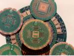
Socket footprints shown in the image above are for the following Yamaichi-built sockets, going clockwise starting from the upper left: 532-pin TAB, 304-pin MCR, a footprint that will accept 3 different PLCCs and a 208-pin QFP. (The socket footprint isn't shown for the fifth daughter board in the picture.)
The signal-related probe points of the tester would touch, skid a tiny distance on the gold-plated lands, and form a metallic bond to the lands. The power supplies were brought in through the halo card. A bracket (not shown) fitted the daughter card to the halo card mechanically, and also electrically, conducting the power supplies through edge contacts (the golden "fingers" shown in the picture above). Please note: Terms used in the expanded photographs are defined in our Glossary.
The boards shown in the picture are very thick for mechanical rigidity (0.13inch thick). The daughter cards are 5.58 inches in diameter. The halo board is essentially the same for every package tested, but with various jumper wire configurations depending on the power supplies used. The daughter cards are specific to the package being tested, but are much smaller than the overall DUT board assembly. Five daughter cards can fit on a printed board panel, whereas only one foot-wide disk would fit on a panel. Thus, this system greatly reduced the cost of DUT boards for the chip manufacturer's testing facility.
DUT boards are designed for the controlled impedance of the tester being used.Trace corners are rounded to reduce noise.
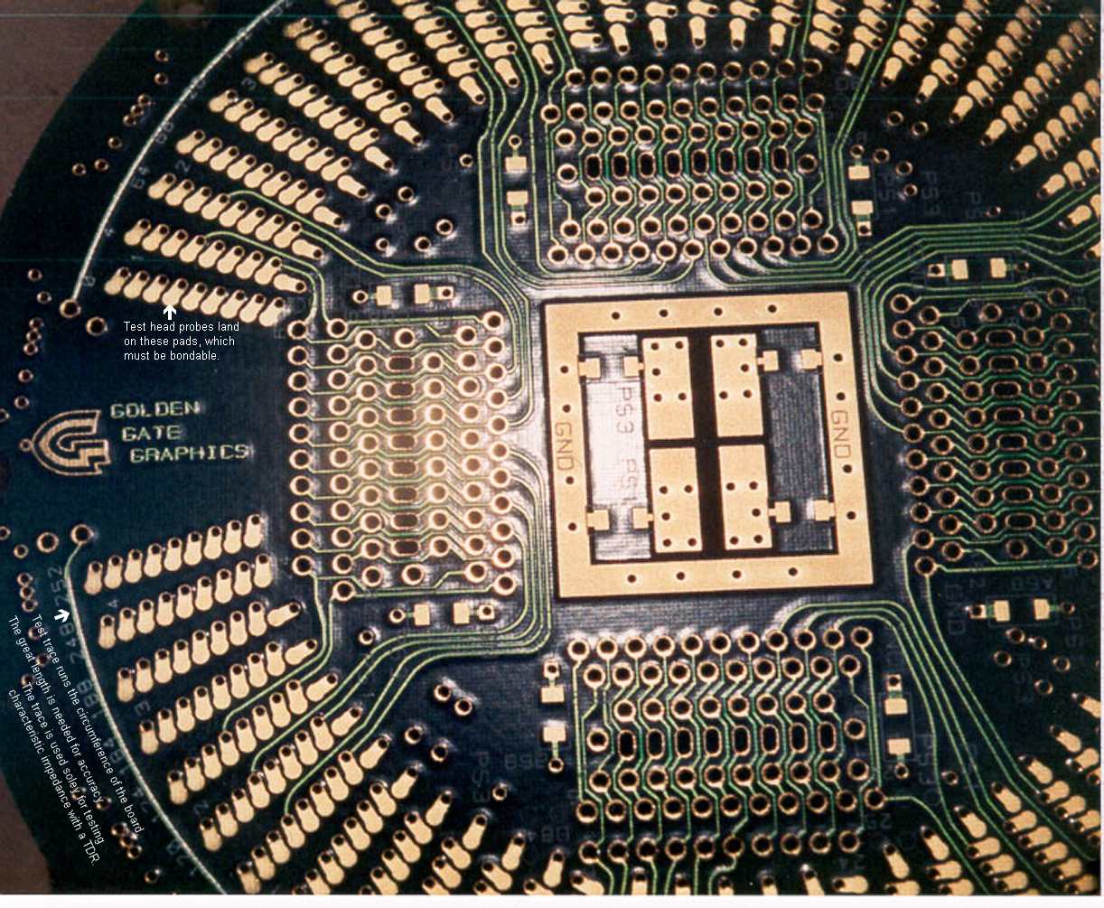
You might notice in the expanded view that some holes of the socket footprint are oval. This is because this socket footprint can accept various sockets, namely 84-pin , 68-pin and 52-pin PLCC sockets. Where the solder-tail pins of different sockets would be too close to have individual round holes, an oval shaped plated through hole was used to accomodate either socket.
The system of having the DUT daughter board fit in a halo board saved money, as mentioned above. And having this daughter board accomodate three different sockets saved even more money.
The surfaces that the test-head probe points connect to are bondable, just as are the bonding pads inside a chip carrier package. This is why the metallic surfaces of a DUT board are golden. The bondable surface is flash gold (also called electroless gold) over nickel. This finish is known among electronic manufacturing services as ENIG.
Golden Gate Graphics designed over a dozen of these daughter cards, of which the chip manufacturer had hundreds built.
A major supplier of zero insertion-force (ZIF) sockets for large fine-pitch chip carriers is Yamaichi. Much of the time spent designing one of these DUT boards was in "building" the thru-hole socket footprint.
Golden Gate Graphics resides in Aurora, a suburb of Denver located in the middle of the
Rocky Mountain Front-Range High-Tech Corridor
, which includes the following
Colorado cities from south to north:
Colorado Springs, Monument, Castle Rock, Highlands Ranch, Centennial, Englewood, Littleton, Denver, Lakewood, Golden, Aurora, Broomfield, Louisville, Lafayette, Boulder, Longmont, Loveland, Ft. Collins and Greeley.
 |
 |
| Full site is mobile responsive as of 3/22/25. Last update: Monday, May 5, 2025.
Copyright © 2025 John Walt Childers, IPC-CID. All Rights Reserved.
Loading phone... | |