Design Rules for High Voltage in Multilayer with Altium Designer 14-22
by John Walt Childers
Use these rules at your own risk. The idea here is to present an approach to a complex problem. The rules below illustrate that approach. They are NOT guaranteed to work for your board. It is ON YOU to experiment with your design rules exhaustively before building your board.
Note: This is an advanced topic and I assume the reader has experience with Altium Designer 's query syntax and its use in design rules.
Multilayer boards have an advantage in high voltage design, because electrical objects on inner layers are well insulated from each other by dielectric. Epoxy fiberglass is a better insulator than air, meaning clearance requirements are smaller. Thus traces can be closer to pads and other traces on inner layers than they can on outer layers for the same voltage difference.
Here is the caveat in Altium Designer's query language: "Multilayer" is a layer name just like "Top Layer" and "Bottom Layer." In trying to implement smaller clearances on inner layers, I did not discover this fact and its importance until I set up numerous experiments, deliberately introducing errors and seeing whether or not they were flagged as such by my design rules. Altium Designer's query syntax does not recognize that "Multilayer" embodies any electrical layer—the syntax is too literal to manage that leap in artificial intelligence.
Altium's default clearance checking rules do function correctly, meaning multilayer objects are compared with mid layer and outer layer objects. However, prior to Altium Designer 23, high voltages require complex rules that use net classes in Altium Designer's query language. Simply put, the query language did not always work well. It has recently been improved by Altium by boosting its artificial intelligence capabilities.
As of Altium Designer 23, it is possible to assign voltages to nets and use these assignments in design rules.
This article is for those of you using earlier versions.
Proof That in Altium Designer 14-22, in Clearance Rules that Use Net Classes, “Multilayer” is a Literal Layer Name and Functions Improperly Unless This is Accounted For in the Queries
A simple rule that didn’t work:
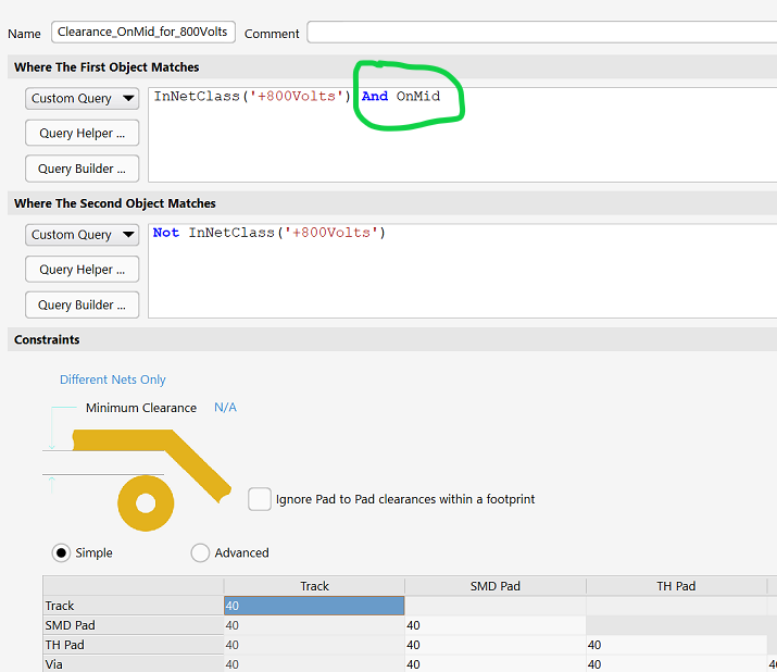
“OnMid” identifies any inner copper layers. This rule should cause a clearance of 40 mils between the net class +800Volts (the net class of the polygon) and copper not in the net class (in this case, the net +INPUT) and on the same layer, including the pads surrounding any plated-through holes (which are on the layer named “Multilayer”).

The rule did not work as expected. Why not? It took some trial and error to find out why. This involved setting up many experiments. Some experiments would detect cases of known clearance violations that were undetected, and others would detect instances of false violations.
The rule was fixed by specifying OnMultilayer. The following images prove that Multilayer was treated in Altium Designer’s net-class-based queries as a literal layer name. Altium Designer had a bug that prevented it from recognizing that if an object was on a multilayer, it was also on a named copper layer such as Top or MidLayer2. This bug occurred when net classes were used as part of the design-rule queries. The bug did not affect simple clearance rules.
- An example of a simple rule is the default Clearance rule, where both the queries use the query “All” as follows:
- Where The First Object Matches
- All
- Where the Second Object Matches
- All
In this type of rule, Altium Designer has no difficulty recognizing that objects on Multilayer will be compared with objects that are on any of the outer or inner copper layers.
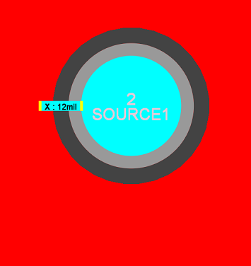
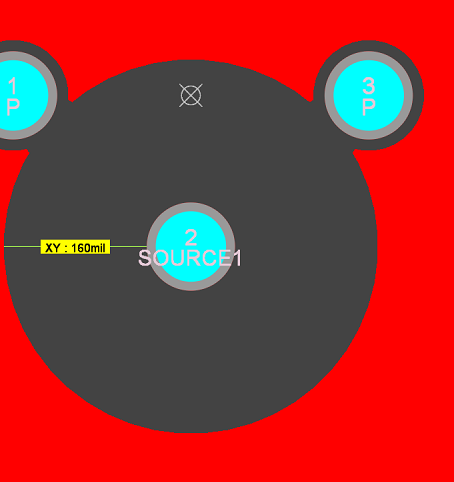
In fact, the above simple query is in the design rule that set the clearance at 12 mils in the above result in Figure 2. The rule for +800Volts, which was properly set to a higher priority than this default rule, was ignored by Altium Designer until the query for the second object specified OnMultilayer.
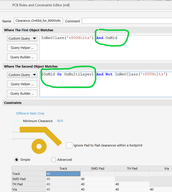
This rule works, now that the second-object query treats Multilayer as a unique literal layer name, not a combination of layers.

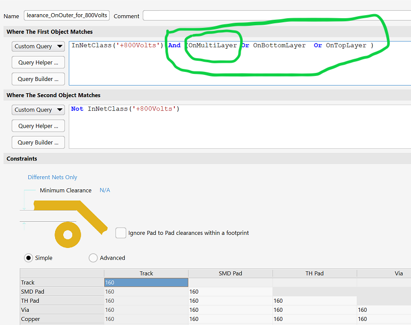
It’s a similar situation for outer layers.
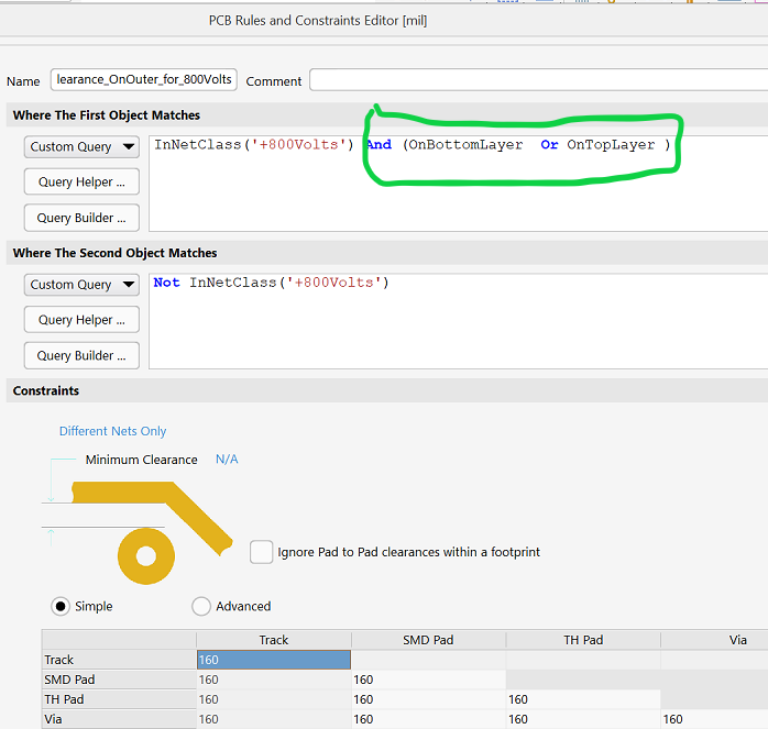
This rule did not function properly.
Example Rules
Here are some examples that show this factor. To set these examples up, let's use net classes for each nominal or worst case voltage: +250 Volts and +750 Volts. This is a multilayer board with both surface mount and through-hole component pads and with all vias going all the way through the board, so there are vias and pads on the layer named "MulitLayer". In looking at these examples, one should be aware that design rule "priority" greatly affects how your rules work as a set. The simple guideline for priority is to set the most common, least specialized rules to the lowest priority. The default clearance rule is always the lowest priority rule.
Warning: If you didn't already know this about Altium Designer's implementation of priority, then this article might be confusing for you. If your head seems to spin while reading this, it would be best if you could go to the Altium forums and wiki for help and learn how to use some simple design rules until you are very competent with that. Then return to this article. If you continue on and become confused, take my advise and do as described just above.
Clearance Spacing Requirements Used Here Are Not Necessarily What Your EE Would Want To Use
Note that for high-voltage, "spacing" refers to clearances used on inner layers, and "creepage" refers to clearances used on outer layers. The terminology can be further muddled even by the use of the word "clearance," which has a special meaning in this subject, that is, the line-of-sight distance between two conductors through air. In this white paper, I am using clearance in its usual since in design rules: The distance between electrical (copper) objects regardless of what layer they are on.
Your clearance numbers for spacing may not agree with mine for these voltages. The amount of spacing used depends on your source data, environment of end use, factors of safety etc. I have used IPC-2221B Generic Standard on Printed Board Design, Section 6, for information on this. Table 6-1 is key. My clearances are slightly more than what would be found in Table 6-1, and section 6.3 for Type B1 (internal conductors) Type B2 (external conductors, uncoated at low altitude). If the electrical engineer wants more clearance, I do what he wants. Also, 2221B applies only to common dielectrics, i.e. woven fiberglass with epoxy-based resin systems. For other materials, you'd need to do some research.
Whatever clearances you settle on, you can adjust that parameter as needed in your design rules.
The Nitty Gritty: Getting Your High Voltage Clearance Rules To Function Properly in Altium Designer 14-22
Compare nets in +750 Volts to all other nets, assuming they are all low voltage (0 to 12 Volt), for now ignoring that 250 Volt objects will be included as part of "all other nets." This set of clearance rules will be given a lower priority than the rules used to compare 750V to 250V. These rule paradigms will work for any voltages--only the actual clearances will change for different voltage differences and for other complexities as mentioned .
Five rules are needed for one voltage difference. We need three rules to cover objects on outerlayers and two more for inner layers.
- Compare objects on "MultiLayer". :
First Object query is InNetClass('+750Volts') And OnMultiLayer
Second Object query is Not InNetClass('+750Volts') And OnMultiLayer Different Nets Only, Minimum Clearance 160mil
Because MultiLayer includes outer layers, this clearance is an "in air" creepage.
Side note: "In air" means on the outer surface of the board, as though no solder mask is used. Solder mask provides very little insulation for creepage purposes, so its presence is being ignored here. - Compare +750 Volt objects on Top layer to other objects on top or multi layer:
First Object query is InNetClass('+750Volts') And OnTopLayer
Second Object query is Not InNetClass('+750Volts') And (OnTopLayer Or OnMultiLayer)
Different Nets Only, Minimum Clearance 160mil
The "OnTopLayer Or OnMultiLayer" is necessary because Altium does not recognize that if an object is on the "MultiLayer" it is also automatically on the "TopLayer". The syntax is too literal for that. Now are you getting my point?
- Compare "not 750V" objects on Top layer to +750 Volt objects on top or multi layer :
First Object query is Not InNetClass('+750Volts') And OnTopLayer
Second Object query is InNetClass('+750Volts') And (OnTopLayer Or OnMultiLayer)
Different Nets Only, Minimum Clearance 160mil
Is this rule really necessary? Yes! This is a case where the caveat mentioned above and regarding "Multilayer" as a layer name in Altium Designer's query language results in us having to write "extra" rules.
- Compare 750V objects on the middle trace layer to other objects on middle or multi layer
First Object query is InNetClass('+750Volts') And OnMid
Second Object query is Not InNetClass('+750Volts') And (OnMid Or OnMultiLayer)
Different Nets Only, Minimum Clearance 40mil
Now in this board design only one of the inner layers is being used for 750 Volt routes. That's why I could get away with using OnMid instead of using the actual middle layer name. If more than one inner layer was used for 750V, then I would have to have a set of two rules like 4 and 5 herein for each layer specifically. If I used OnMid, it could be comparing objects on one of the inner layers with objects on another one of the inner layers, which would be pointless. - Compare "not 750V" objects on the middle trace layer to +750 Volt objects on middle or multi layer.
First Object query is Not InNetClass('+750Volts') And OnMid
Second Object query is InNetClass('+750Volts') And (OnMid Or OnMultiLayer)
Different Nets Only, Minimum Clearance 40mil
This brings up why priority is so important. Rules 4 and 5 here, being for an inner layer, could result in a clearance violation not being flagged for objects on an outer layer if they were multilayer objects, like vias. So Rule 1 above will have to be a higher priority than these last two rules.
The Above Set of 5 Rules Sets the Pattern
I am not going to go through another set of rules for clearance between 250 Volts and 750 Volts. Suffice it to say that it will require another five rules for the voltage difference of 500 Volts and your "Not InNetClass('+750Volts')" query object will change to "InNetClass('+250Volts')." Any entire set of rules comparing 750 Volt objects to 250 Volt objects will have to be a higher priority for that set than the set of rules above, which compare 750 Volts to all other nets. This would be a more specialized set of rules, so it gets a higher priority. Another way to say that is that a smaller set of objects meets the 750/250 Volt set of rules than the set in 1-5 above, so it would need a higher priority.
There could be many more rules needed, of course. I hope the above are enough to get you started thinking about all the possibile comparisons needed to cover your board.
High Voltage Clearance Between Layers
Traces might cross over each other on adjacent layers. At least high voltage traces will cross over ground plane. You need to know what the clearance requirements are for your dielectrics and thickness of separation for the worst case voltage difference and set that as the minimum dielectric thickness between layers. You wouldn't use the same clearance for that as for the inner layer trace-to-trace rules (40mil in this example), but would use something less. On this high-voltage board, 10 mils was used for all dielectric thicknesses. Warning: That is NOT a recommendation. Layer-to-layer clearance voltage requirements are covered in UL 60950.
Complex Subject
High voltage is a complex subject when you consider effects such as AC and crosstalk. If you do a Google search on "high voltage site:altium.com" you can find many articles by Altium on these complexities, so I recommend that. However, you won't find an article on how to use Altium Designer's design rules for nailing down your clearance rules as I've described herein.
Altium techdocs don't teach these techniques.
I searched and searched for just such an article and never found one. I had to make these discoveries myself.
Summary
Objects of different voltages on one of the two outer layers need to be compared through a set of three rules:
- The first voltage on MultiLayer to the second voltage on MultiLayer
- The first voltage on the specific outer layer to the second voltage on the same outer layer or MultiLayer
- The first voltage on the specific outer layer or MultiLayer to the second voltage on the same outer layer
Objects of different voltages on one of the inner layers need to be compared through a set of two rules:
- The first voltage on the specific inner layer to the second voltage on the same inner layer or MultiLayer
- The first voltage on the specific inner layer or MultiLayer to the second voltage on the same inner layer
Well, I imagine that most people who tried to read this were bored to tears and left their computers. Maybe even had some beers. If you read this far, it could only be because you have battled with high voltage multilayer boards and know how painful it could be if they don't come out right. We're in the same boat.
by John Walt Childers, IPC-CID
21 March 2014, revised to include proof on 27 October 2024


